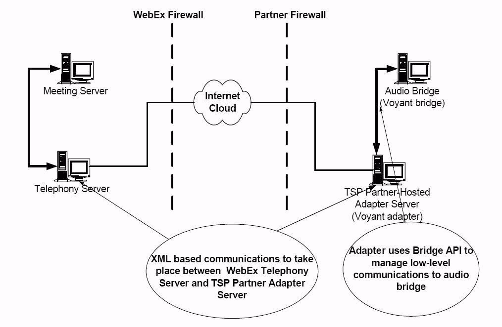
This section provides an overview of the TSP (teleconferencing service provider) architectural elements.
For more information about the TSP calls referenced in this chapter, refer to API Messages Initiated by WebEx Server
Key Architectural Features
Some of the key architectural features of the TSP Bridge are:
- XML-based.
- SSL (Secure Socket Layer) over IP cloud.
- Works independently of WebEx Meetings URL API and XML API.
- Functions across the public Internet.
- Integrates with each user's network elements such as proxy servers, firewalls, security servers, VPN servers, and load balancers.
Bandwidth Requirement
T1 is desired and a 256K connection is considered minimum.
Basic Architecture
WebEx Meetings servers provide Web meeting services hosted by WebEx Meetings and located inside the WebEx Meetings network. Telephony bridges providing voice conferencing services are hosted by a TSP partner and are located inside the TSP partner's network.
WebEx Meetings servers talk to the bridge through API calls over the internet with an HTTP/HTTPS protocol. Each side must have their own Web server installed to process the calls and requests. API messages passing between the two sides are XML formatted.
The API between WebEx Meetings and the TSP partner has a generic definition with basic telephony functionality. Implementations of the functionalities are specific to the type of bridge used. Thus, an adapter application (or adapter) is required between the TSP partner Web server and the bridge to convert generic API calls to the bridge's own API calls.
Messages initiated from the WebEx Meetings side are routed to the adapter using information found in the WebEx Meetings telephony domain. Conference-related messages initiated from the adapter side are routed to the WebEx Meetings server using the URL given in a previously received Create Conference message. See W2A_CreateConference for more information.To achieve higher security, SSL (Secure Socket Layer) boxes can be placed in front of the Web server on the TSP partner's side.

Note:The Voyant Adapter in the illustration above is an example of a WebEx Meetings application integrating with a Voyant Bridge.
System Architecture with Fail-over Feature
WebEx Meetings TSP architecture is designed to support different system fail-over and redundancy configurations. There are two parts to server redundancy:
- WebEx Meetings internal system redundancy
- TSP partner system redundancy
Two examples of redundancy implementation follow. The WebEx Meetings server supports both using different server configurations as specified in a configuration file.
Transparent Redundancy Design
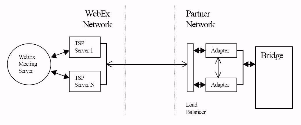
On the WebEx Meetings side, there are multiple application servers (i.e., TSP servers) running simultaneously, all of which communicate with the single adapter (or load balancer.) In the case where one TSP server goes down, traffic is automatically re-routed through the other servers.
In this design, the adapter's redundancy is transparent to WebEx Meetings. WebEx Meetings servers always communicate with the adapter(s) through a URL or host name. They do not need to know which adapter they are actually communicating with, and can consider them as a "single" adapter.
A load balancer can dynamically dispatch the WebEx Meetings requests to different adapters based on specified criteria. If one adapter fails, it will not be noticeable from the other end of the load balancer.

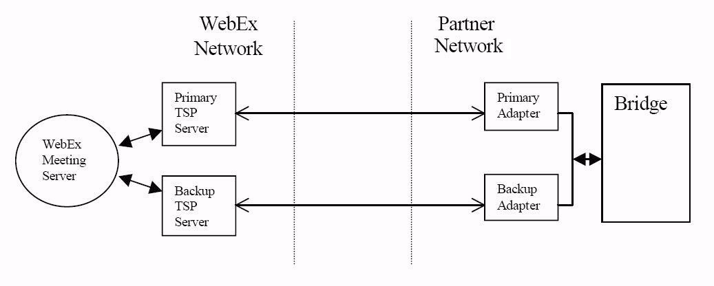
Parallel Redundant Channels Design
This design is simpler. In a Parallel Redundant Channels design, each TSP server is configured to communicate with a dedicated adapter. The WebEx Meetings meeting server communicates with the bridge through the parallel channels. If a TSP server or an adapter goes down, the meeting server uses the other channel for new conferences. No balancer is needed in this design.

